| Attachment | Size |
|---|---|
| 20 KB | |
| 42.74 KB | |
| 41.49 KB |
I'm having some rf issues that I'm having problems diagnosing.
We have an EVR cmts running 2 upstream cards.
Here is the config:
Downstream:
description = DOCSIS 30.34 Mbps
admin-status = up(1)
channel-id = 128
frequency = 0
width = 6000000
modulation-type = qam64(3)
interleave = taps32Increment4(5)
annex = annexB(4)
registered-cms = 96
active-cms = 38
average-bitrate = 3333246
DS frequency is digital channel 32 ( i forget what that is in MHz, but there aren't any other channels within 4 channel widths on either side)
Upstream:
id | admin status | modulation frequency | width | profile | slot size | rng backoff start | rng backoff end | tx backoff start | tx backoff end
------- ------ --------- ------- ---------- ---- ------- ------- ------- -------
1 up 30000000 3200000 1 8 1 3 2 9
2 up 20000000 3200000 1 8 1 3 2 9
group id | snr |registered cms | active cms | bitrate | auto iri |nominal rx-power | tolerance
----- ----- ---------- ------ ------- --------- -------- ---------
1 28 53 23 74609 1 0 6
1 24 43 12 79277 1 0 6
upstream modulation:
iuc | control | type | preamble start |preamble len
-------------------- ------------------ -------- -------- --------
request(1) active(1) qpsk(2) 64 64
initial ranging(3) active(1) qpsk(2) 0 128
periodic ranging(4) active(1) qpsk(2) 0 128
short data(5) active(1) qpsk(2) 48 72
long data(6) active(1) qpsk(2) 40 80
diff-encode | fec err-cor | fec code-len | scrambler seed | max burst | last code-word | scrambler
----------- ------- -------- --------- ----- --------- ---------
false(2) 0 16 338 0 false(2) true(1)
false(2) 5 34 338 0 false(2) true(1)
false(2) 5 34 338 0 false(2) true(1)
false(2) 5 75 338 14 false(2) true(1)
false(2) 8 220 338 0 false(2) true(1)
This issue we are having is with modem return path power. We have balanced the amps several times, but it's still giving the same issues. Both our downstream and return path seem to be all over the place and there doesn't seem to be any geographic correlation. Below is a snapshot of the signal levels reported by the modems. First thing to notice is yes, it is running hot on the downstream. When we first installed it, we (unknowingly) had a bad amp that was knocking down signal. We haven't changed the padding on the upconverter yet. We are experiencing about 10 modems not able to register because of too much padding on the return path (yet their downstream signal is fine). We did just swap out another amp (resulting in this result below) which improved some of them, but there are still some that didn't make the list because they are stuck ranging (no IP to walk).
When we first installed the CMTS, there was a cut cable that shorted and back fed power through the plant. It ended up frying one amp and popping the fuse in the power inserter. Like I said, our (TV) rf tech has been over this plant about 4 times and he can see the issue but can't find anything that would be causing the discrepancy. These modems are all over the plant and not clustered to any one leg.
Any suggestions on what to look at?
edit: it screwed up the formatting, so I attached the signal info as an excel file
I've taken a quick look at your excel chart. You seem to have a fair amount of modems transmitting below 35db and virtually none above 47. This would indicate to me that your return could probably use some padding; perhaps 7db or so. That would bring up the transmit levels of the modems and lower the return noise -- overall increasing your return SNR. Optimal transmit levels for modems are generally ~39-49db -- high enough to avoid noise from the units themselves, and low enough to avoid situations where many modems are at max power. Modems transmitting too low (in the 20's) may have too much internal noise in their signal resulting in poor return MER for the individual unit. Modems transmitting too high causes harmonics, exasperates microrelections and creates general plant noise.
Note that you'll always have a wide spread of rx/tx levels as tap values, splitter configs, and cable loss are always different in subscriber homes. Some modems might be hanging off an 8 way transmitting at 55db, others off a 2 way transmitting at 29. There's no way to predict what you'll actually see. The best way to manage those levels is by working with your senior RF guys and putting together an installation design anticipating loss from taps, cable and splitters, and then *always* following the design when installing data products. For example, you'll probably want to determine the min/max acceptable tx/rx levels at any given tap (regardless of depth of amp cascade), the expected loss to the splitter, and then how a data unit like a MTA, modem or digital set top box should be configured from the splitter.
Obviously designs for MDUs will be different than single family homes, etc, so a bit of thought has to go into it. For example, you could create a requirement for modems to always acquire at ~+13rx, +33tx at any tap. Maintenance guys might have to balance amps, change face plates or split a cascade as necessary. A home with 1+ analog TVs, 1 digital set top box and 1 modem could have a requirement of a 3-way splitter as the initial contact point, with the modem straight off the low loss leg, the digital set top box off the 2nd leg, and all analog TVs off the 3rd leg using additional splitters as needed. If you're a HFC plant, the laser inputs have to be set up properly to match the expected input power, etc. If they're underfed, you'll have poor return MER, overfeed & you'll clip. It really does require a lot of work to really put together a proper end to end design, but it pays off bigtime.
I can tell you from experience that NOT enforcing a standard tap requirement and installation design will result in years of heartache. Modems behind 3 splitters, hanging off 8 ways, etc -- will always eventually come back to you in the form of angry subscribers and endless truck rolls.
Anyway -- my first suggestion is for you to plot your tx levels in to a bell curve, and then figure out how to move the center of your bell to about +44db with return padding at the CMTS. Also, find the CMTS MIB for plotting upstream SNR, and corrected/uncorrected FEC. Your plot of uncorrected FEC percentage on the return will be the ultimate "truth" on whether or not everything is working correctly. You want to stay well under .1% uncorrected packets - once you start getting above that, TCP speeds will suffer as windowing falls apart, and realtime stuff like VoIP & gaming will perform poorly.
Hope that helps-
thanks yoyo, that does help quite a lot.
You are right, this is very frustrating. Especially when I have 3 'senior' RF techs (who have never worked with Data) telling me the plant is perfectly balanced. I have been tracking FEC and SNR, and on average our total symbol errors are under .1% (if I'm reading it right) with the uncorrectible errors being a smaller percent, but SNR averages low 20's (22) fairly consistently. I'm hesitant to pad the return path more, because there are 4 or 5 customers that aren't able to connect (didn't show up in the stats) because the their return path is too padded. When I histo the raw tx power, I actually get a bimodal distro centered on 38 dB and 47 dB. Should I attempt to normalize the TX power with the RX power to limit the effects of combined loss?
Another question... This issue only started happening after swapping out CMTS's. We were using a C9 networks CMTS, which centers it's return path at -12dB. Under that system, we had no issues with modems registering, but did have some issues with noise. The new CMTS is an EVR (Coresma) unit which by default centers the return path a 0 dB. I did try to drop it to -12, but SNR's were in the teens.
I think you hit the nail on the head with the enforcing standard tap requirements, as each building (or section of building) is fed off an 8-way, where each run off that tap feeds one unit. In the unit is anything from a 2 way to a 6 way splitter to feed all of the wall outlets... then throw in any customer supplied splitters. I'm just not sure why it is mattering now, when it didn't with the old (cheaper and crappier) unit.
Can you clarify what standard tx and rx levels for a modem should be and how far off of that do you have to go before running into problems?
Hi-
Something I forgot to bring up is the return target level to be configured at the CMTS... Are you saying that the former CMTS was using -12 as the target level? That is really low -- I'd think that any noise at all would cause lots of issues. Zero or +1db is the desired target level I've been accustomed to using on Moto CMTS gear for years for 3.2mhz wide 16qam. You want to be feeding your return ports with appropriate power from the modems or errors go up significantly. With a good overall design, quality install jobs and fair plant conditions there's no reason why you shouldn't see high 20's or 30's MER/SNR reported from the CMTS. Although your figures are a bit low, uncorrected symbols seem like they're well under control so there's no reason to panic.
DOCSIS spec says modems should operate at -15 to +15 RX power; it would stand to reason the 0db would be the target. However, I've found that many modems suffer under high power RX conditions -- taking errors at +12dB but running fine at -12, etc. -4dB seems to be a good target average for a design as it still provides plenty of headroom in both directions.
Transmit levels can vary depending on your design; specs say that modems should be able to transmit anywhere between +8 to +55dB at 16QAM. However, modems do put out a small amount of internal noise that can creep into the teens depending on model. Because of that, it's desirable to have enough padding so that the lowest of your modem transmit levels are above 28dB or so (keeping the peak power away from the internal noise signature). The sweet spot is in the low 40's as it gives you plenty of headroom in either direction. You'll find that the cable plant attenuation can increase with temperature. Modems transmitting near peak power (in the 50's) can start falling offline in the summer months so it's important to have installers leaving modems under 48dB - well away from their max.
Although you're hesitant to make changes that could drop a few modems, it's likely that that those units really are in need of reconfiguration or repair. Lowering the required transmit power for everyone might let a couple more modems with significant loss back onto the plant -- but SNR may suffer overall. The basic concept with padding is that the attenuation pushes noise down and modem transmit levels up - giving a decent overall SNR. It just has to be measured to prevent the average TX level from getting too high.
Since your RF guys are telling you that the plant is balanced, the only explanation for the large range of modem transmit levels is the quality of the install jobs and the random customer splitters/cabling. You can't control any of that yourself, so I think that someone is going to have to bite the bullet & go out there to fix stuff that's way out of spec. Enforce your installation specs and check levels on new installs the day of (and the day after) they're complete to make sure they were done correctly.
It's just not possible to effectively deal with modem attenuation that varies wildly from unit to unit. It sounds like you've actually got it dialed in as best as you can at the moment. However, I'm not sure why you're having more trouble than before -- did you go from QPSK to 16QAM, or 1.8Mhz wide to 3.2? Anyway - as to your question about normalizing levels; I'd definitely make an attempt to do the return only. Downstream carriers should be set to match other forward carriers/QAMs peak power per hz. You don't want your carrier any higher or lower than those adjacent. 256QAM is generally easy to do as long as your modems are reporting mid/high 30's on the DS SNR.
BTW - this hardware guide for a Cisco UBR shows a lot of the general DOCSIS specs and how signals should look from the head end in comparison to analog carriers:
[url]http://www.cisco.com/univercd/cc/td/doc/product/cable/ubr7100/hig7100/hi...
thanks for that info.
yes, the C9 cmts targets -12 on the return path and yes we did have signal issues (a good day was an SNR of 21). It's one of the reasons we are upgrading.
We did figure out the issue at one of our sites. The site was digital video before data was added, and when they added data, they fed the combined signal through a digital mixer then out to the plant. When we installed the new system, we just used the existing connection to the plant. The digital mixer was dropping the return to -8 regardless how strong it was. We re configured it, making the diplexer the first thing the return hit after comming off the plant, and everything came up 10x healtheir then before. Unfortunately the return isn't passing through the mixer at this particular site.
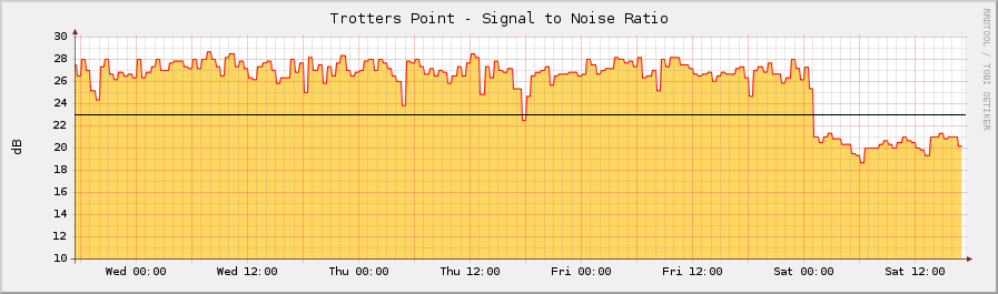
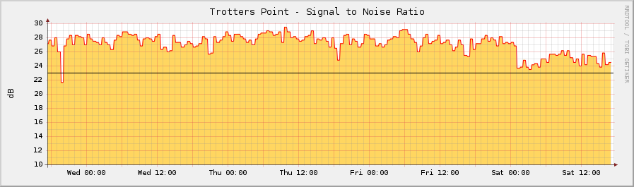
I would like to believe that everything in the plant at our problem site is fine, but I'm still observing strange things going on. For instance these are plots of SNR for the two upstream cards from the past 4 days. There was no change in the plant over the course of this time period. They are attached at the top with the other file
Just an update.
The primary issue turned out to be a bad splitter in the head end. Since Data was added to this site after the video, they had just been running the data separately through a 2-way splitter off plant (one branch data, one for video). We swapped it so that the combined side of the diplex is directly connected to the plant, and the broad spectrum of transmit powers tightened up considerably. We traced that drop in SNR to a line amp feeding one and a half buildings (yea one and a half... no wonder it was hard to isolate). Replaced the module and the pads, and the building came back up.
Thanks again for all your help.
Nice reading!
What is the best and most used RF architecture used for today needs Voip and hispeed internet, star like 2-3 apms in line and star in the building with spliter our tree with flour taps ? What kind of experiance you have with amps,cables and spliter/taps what to use?
There is not much RF topics but it gives bigest headaches :).
I'm actually an IP/data guy but have been managing docsis networks for about 7 years now. Most of my experience has simply been from trial and error -- some true RF engineers could probably give you much better hardware recommendations than my own. However, I've got some reading suggestions that I think would be appropriate for anyone trying to deploy DOCSIS networks:
"Broadband Cable TV Access Networks: From Technologies to Applications"
[url]http://www.amazon.com/Broadband-Cable-Access-Networks-Technologies/dp/01...
And for anyone doing Packetcable based VoIP:
"Digital Telephony Over Cable - The PacketCable Network"
[url]http://www.amazon.com/Digital-Telephony-Over-Cable-PacketCable/dp/020172...